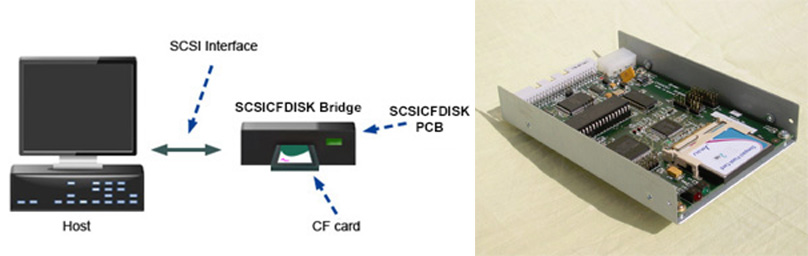
Solid State replacements for legacy SCSI Disks
- The SCSICFDISK PCB is a SCSI solid state disk that uses a standard Compact Flash (CF) Card as its storage. The CF card is plugged into the 3M CF socket at the end of the PCB and this is presented as a regular SCSI disk to a Host via the SCSI interface the other end of the board.
- The PCB mounts in a standard 3.5″ form factor tray. It requires 5V only which is supplied via a standard disk power connector.
- The 3.5″ form factor disk has a standard SCSI1/SASI/SCSI2 interface can be configured to emulate & replace those hard-to-find SCSI disks/MO/Floppy drives for legacy systems.
- Data is stored on an industry standard Compact Flash (CF card), which can be easily removed. The CF card can then be plugged into a PC and the data archived.
When connected to a SCSI Host, the Host sees the SCSICFDISK PCB as a regular SCSI disk.
The SCSI bridge PCB carries its microcode in Flash, that can be simply updated via the SCSI or Serial ports. It has an optional standard display module interface to drive a 2 line by 16 character backlit, LCD display.
Disk emulations exist for the following systems:
Applied Materials, AS/400, Cannon, DEC VAX, UVax and PDP-11, Data Technology Corp. DTC520B Dutch Signaal, Encore, Evans & Sutherland, HP 9000 series 800, HP 9000 series 500, HP 9000 series 300, HP 1000 A Series, HP-IB Bering, I/O systems OMTI DTC51, Nicholet, Honeywell Measurex, MX-OPEN, Rosemount RS3, Sercel, Sun Spark, Thompson CSF, ABB Advant Operator Stations, HP B132L+ HP B180L, and several Telco host applications including Ericsson and Siemens EWSD.
And for the following Operating Systems:
HP-UX, HP-RTE, HPL, VMS, IRMx, OS/400, GCOS, BOSS, VXworks, OS2, DEC VMS, RSTS, OSF, MXopen system QCs, UNIX, Solaris, SASI
The unit can emulate a standard SCSI disk, a SASI disk, an MO removable drive or a Floppy disk. Emulated Disk Sector sizes can be 256, 512, 768., 1024. 2048, 4096 bytes.
SCSI 2 transfer rates of (up to) 10 Mbytes/sec, and disk capacities only limited by current CF cards (up to 64 GB as of 2011)
Garson Industries aim the product as a low-cost way to give extra life for Legacy Hosts which would otherwise need to use unreliable second-hand disks.
Current Fixed disk Emulations:
AVASTOR, Bering, COMPAQ, Conner, CDC, DEC, EPSOM, Fujitsu, Hitachi, HP, IBM, IMPRIMIS, ITOCHU, KALOK Maxtor, Micropolis, Miniscribe, Miscellaneous, NCL NEC, Newbury Data, OPTIMA, ORCA, Plus Develop, Quantum Rodime, Seagate, Sequel, SIEMENS NIXDORF, SINGAPORE, Syquest, TEAC, TOSHIBA, Western Digital, YE DATA
DP-3055, DP-3110, DP-3221, DSP-2022, DSP-3053, DSP-3085, DSP-3107, DSP-3133,DSP-3160, DSP-3210, DSP-5200, DSP-5300, DSP-5350, RZ25L, RZ26, RZ28VA, RZ29VA, RZ73, RZ74, SP-3107, VP-3107, VP-3215
Bering
COMPAQ
Conner
CP30170E, CFA-1080S, CFA-170S, CFA-810S, CFN 170S, CFN250S, CP30080, CP30100, CP30170, CP3040, CP3040, CP3360, CP3540, CP340
CDC
Sabre, Imprimis, CDC 94171, 94161
WREN VHF 94161 , 94171, RNR 94601, VIFH 94601
SWIFT 94354
DEC
RZ23, RZ25L, RZ26, RZ28, RZ29, RZ73, RZ74, DP-3055, DP3110, DP3221
DSP-3053, DSP-3085, DSP-3105, DSP-3107, DSP-3133
DSP-3160, DSP-3210, DSP-5200, VP-3107, VP-3215
EPSOM
HMD-726A
Fujitsu
M16033SAU, M1606SAU, M1636HA, M1636SA, M1638HA, M1638SA, M2244SA, M2244SB, M2244S, M2245SA, M2245SB, M2245S, M2246SA, M2246SB, M2246S, M2248SA, M2248SB, M2248S, M2249SA, M2249SB, M2249S
M2261H, M2261HA, M2261HB, M2261SA
M2262H, M2262HA, M2262HB, M2262SA
M2263H, M2263HA, M2263HB, M2263SA
M2266H, M2266HA, M2266HB, M2266SA, M2266SB
M2611S M2611SA, M2611SB
M2612ES M2612ESA, M2612ESB, M2612S M2612SA
M2612SB, M2613ES M2613ESA, M2613ESB, M2613S
M2613SA, M2612SB
M2614SB, M2614ES M2614ESA, M2614ESB, M2614S
Fujitsu M2614SA, M2614SB
M2615SB, M2615ES M2615ESA, M2615ESB, M2615S
M2615SA, M2615SB
M2616SB, M2616ES M2616ESA, M2616ESB, M2616S
M2616SA, M2616SB
M2617SB, M2617ES M2617ESA, M2617ESB, M2617S
M2617SA, M2617SB
M2618SB, M2618ES M2618ESA, M2618ESB, M2618S
M2618SA, M2618SB
M2622F, M2622FA, M2622FB, M2622H, M2622HA
M2622HB, M2622S, M2622SA, M2622SB
M26223F, M2623FA, M2623FB, M2623H, M2623HA
M2623HB, M2623S, M2623SA, M2623SB
M2624F, M2624FA, M2624FB, M2624H, M2624HA
M2624HB, M2624S, M2624SA, M2624SB
M2634F, M2634FA, M2634FB, M2634H, M2634HA
M2635S, M2636S, M2637S
M2652S, M2652SA, M2652SB
M2653S, M2653SA, M2653SB
M2653H, M2653HA, M2653HB
M2654S, M2654SA, M2654SB
M2654H, M2654HA, M2654HB
M2654HD, M2654HDA, M2654HDB
M2681, M2682, M2684,M2691, M2692
M2693, M2694, M2704, M2909, M2915
M2927, M2932, M2934,M2948, M2949, M2952
M2954, MAA-3182, MAB-3091
M2512A, M2266SA, M2516S, M1606S-256, M2616S
M2934S, MAN3367MC, MAN3184MC, MCE3064SS,MCR3230SS, M2954S MCM3130SS
Hitachi
DK211C, DK312C, DK315C, DK318C, DK319C, DK326C
DK328C, DK329C, DK512C, DK515C
DK516C, DK517C
HP
97540, 97544, 97548, 97556, 97558, 97560
C2233, C2234, C2235, C2244, C2245, C2246, C2247-300
C2490A-001, C2490A-XXX, C3007-XXX, C3010-XXX, C3323A-XXX
C3724, C3725, D3581, D3582, D3583, C3325A-XXX, C3324A-XXX
IBM
DPS-31080, 0661,0662, 0663, 0664, DCAS-XXXX, DCHC-XXXX
IMPRIMIS
Elite 97501, SWIFT 94335, 94351, WREN III 94161
WREN VHH94221
ITOCHU
YD-3081B, YD-3082B, YD-3083B, YD-3084B
KALOK
KL-341
Maxtor
7040S, 25252S, 7135S, 7245S, 7290S, LXT-100S
7060S, 7120S, 7546S, 7345S, EXT-4175S,EXT-4380S
LXT-340, LXT437S LXT-535SY, MXT-540SL, P0-12S, P1-17S, MXT1240, XT-8760, XT-3280, XT-4170, XT-4380S
XT-8380S, XT-8702S, XT-8706S XT-8800S, Maxtor Panther
Micropolis
1050,1373, 1373A,1374, 1374A, 1375,1574-7, 1574-8
1574-9, 1574-10, 1574-11, 1577-12, 1577-13. 1578, 1578-14, 1585-8, 1585-9, 1886-10,1886-11, 1887-12
1887-13, 1888-14, 1888-15, 1594-7, 1595-8, 1595-9
1596-10, 1596-11, 1598, 1624, 1673, 1674, 1683
1684, 1760, 1775, 1908, 1924, 1926, 1936, 1991
2105, 2108, 2205, 2207, 2215, 3221, 3387, 3391 4110, 4221, 4341, 4345NS, 4421, 4743, US0050-03-5,1588, 3243, 1684, 2112
Miniscribe
M7060S, 8051S, M9380S
Miscellaneous
AT150S, AT155S, AT320S, LAN180S, LAN320S, LAN650S
MAC195, PS320S, PS650S
NCL
9121S, 9220S
NEC
D2831, D3811, D3813, D3815, D3817, D3823, D3827, D3841 D3843, D3847, D3855, D3856, D3872, D3881, D3895, D3896
D5852, D5862, D5882, D5892, D5894, SD2384S
Newbury Data
ND340SD, P0-12S
OPTIMA
DISKOVERY
ORCA
760S, OT507-S, 510-S
PLUS DEVELOP
IMPULSE PTI PT238S, 357S, 376S
Quantum
Atlas, ATLAS II, Atlas III, Atlas IV, Bigfoot CY Bigfoot, Capella , EMPIRE, Fireball, Maverick
Fireball 1080S, 1280S, 540S, 640S, ST4320S, TM1280S
Prodrive, ,Viking, Godrive, 40, 60, 80, PRODRIVE
Grand Prix, Lightning, Trailblazer, SIROCCO, GRS GLS, GF40S022, VP-3107, VP-3180
VP-31080, VP-31110, VP-3210, VP-3215, VP32210
VP-34360, VP-39100, VP-34280, XP-31070, XP-32140
XP-32150, XP-32151, XP-32181, XP-32275, XP-34300
DP-3221, DSP-3053, DSP3105, DSP-3107, DSP3133
DSP-5200, DSP-5300, DSP5350, EMPIRE 1080
EMPIRE 1400, EMPIRE 2100, EMPIRE 540, Saturn, Daytona
Rodime
RO3085S, RO3089T, RO3139T, RO3199
RO3259T, RO5075S, RO5125S, RO5180S
RO652A, RO752A
Seagate
ST1057N, ST1090N, ST1096N, ST1102N, ST1111N, ST11200N, ST11201N, ST1126N, ST1144N, ST1156N, ST1162N, ST11700N, ST11710N, ST11750N, ST3600N
ST3610N, ST3620N, ST36530N, ST3655N, ST39140N
ST410800N, ST41200N, ST41520N, ST41600N, ST41650N
ST41651N, ST4182, ST4192N, ST42000N, ST42101N
ST423451, ST42400N, ST43400N, ST43401N, ST4350N
ST4376N, ST4383N, ST4385N, ST4766N, ST4767N, ST52160, ST5660N, ST9096N, ST9235N, ST9252N
ST11750N, ST11751N, ST1186N, ST11900N, ST11950N
ST1201N, ST1239N, ST12400N, ST12401N, ST12450
ST12550N, ST12551N, ST125N, ST138N, ST1400N, ST14207N, ST1480N, ST1481N, ST15150, ST15230N
ST157N, ST1581N, ST1830N, ST18771N, ST1910N
ST19171N, ST1980N, ST2106N, ST2125N, ST2209N
ST224N, ST2383N, ST2502N, ST251N, ST277N, ST278N
ST296N, ST3057N, ST3096N, ST31051N, ST31055N
ST31060N, ST31080N, ST31200N, ST3123N, 31231N
ST31250N, ST3144N, ST31930N, ST32105N, ST32107N
ST32109N, ST32151N, ST32155N, ST32171N, ST32271N
ST32272N, ST32430N, ST32550N, ST325N, ST3285N
ST3390N, ST34217N, ST34371N, ST34501N, ST34555N
ST3457N, ST34572N, ST3500N, ST3550N
ST5660N, ST4350N, ST3283N, ST34520N, ST39173, ST4371, ST31250WC/DC, ST32550N/ND
ST32550W/WD, ST32550WC/DC, ST32430N/ND, ST31230N/ND
ST31250N/ND, ST31250W/WD, ST3300007LW/LC
ST3146707LW/LC, ST373207LW/LC
Barracuda 2LP, Cheetah, Hawk
Medalist 8641 (ST38641A), Medalist 6531 (ST36531A)
Medalist 4321 (ST34321A)
Medalist 3221 (ST33221A)
Medalist 1080SL
Medalist Pro Model 9140N
Seagate Maxtor Atlas KW036L4, KW073L8, KU018L2, KU036L4, Seagate Maxtor Atlas KU073L8, KW018L2
SEQUEL
SEQ-4170S, SEQ-4380S, SEQ-5350S, SEQ-5400S
SIEMENS NIXDORF
2200, 2300, 4410, 4420
SINGAPORE
3283, 3387,3391,4743
SYQUEST
3105S, 3270S
TEAC
SD-3105-00, SD-3210-00, SD-3240-00, SD-340-04
SD-340H-00, SD-380H-00
TOSHIBA
MK-1926FBV, MK-234FB, MK-438FB, MK-538FB
WESTERN DIGITAL
SC-8320, SC-8400, SP-4200F, PIRANHA
WDE2170-XXXX, WDE4360-XXXX, WDE9100-XXXX
YE DATA
YD3081B, YD3082B, YD3083B, YD3084B
Current Removable,Floppy and MO emulations
DEC, Fujitsu, Hitachi, HP, IOMEGA, Konica, Maxoptix, Olympus, Pioneer, Ricoh, SONY, SYQUEST, TEAC
RWZ01, RWZ53
Fujitsu
Dynamo 640SE DynaMo1300SCSI, 2300SCSI, MCR3230SS, MCJ3230SS MCM3064SS,MCE3064SS,MCF3064SS, MCM3130SS
M2511A, M2512A, M2513A, M2512A0E, M2513P, M2541A
MCB3064SS, MCC3064SS, MDC3064SS
Hitachi
OD172
HP
C1716T,C1716C, C2550T, 9100MX, C1113, C1114, 5200EX
C1300
IOMEGA
ZIP, Z100Si, JAZ, V1000si, V2000si, Iomega Beta-20H
Konica
OMD-19060, OMD-7071,OMD-7060,OMD7061, OMD-7062
OMD-9060, OMD-9061, OMD-9062, OMD-9063, OMD-6020
Maxoptix
T6-5200, C7369, T5-2600, T3-1300, T4-1300
T7-9100, RXT-800S, TMT5-2600, Tahiti
Olympus
MOS300, MOS320, MOS-540E, PowerMO 2600 SYS.230 MOS331E14, MOS330E
Pioneer
DE-UH7101 DE-U7101
Ricoh
RO-5030EII, RO-5030E, RO-5060E, RO-5061E
Sony
SMO-S501, SMO-C301, SMO-F551, SMO-F541, SMO-F561
RMO-S551, SMO-F521, SMO-F544, SMO-F531, SMO-D501
SMO-E501, SMO-E511, SMO-F521, SMO-S521
SYQUEST
EZ135S, EZ230S, SQ3105S, SQ3270S, SQ5200, SQ555, SYJET1S
Teac
FC-1, FD-235HS
Available in various form factors, with CF eject header, and several subsystem styles.
Overview
- Form Factor: 3.5″ x 1″ hard disk form factor, industry standard hole mount positions M3 threaded.
- Interface: Compliant with SCSI2 standards – ANSI X3. 131-1994.
- Mounting: Any orientation.
- Connector: Standard SCSI 50-pin, Single-Ended (SE). HVD adapter daughter card available.
- CF Card compatibility: Type 1 CF cards via a CFA approved 3M CF socket.
- Ejector: Ejector Option for easy removal of CF card.
- Retainer: Retainer clip option permits stability for mobile and in high vibration applications.
- Reliability (MTBF): in excess of 1,000,000 hours (and counting) (empirical data).
- Parts that wear: CF card eventually wears-out, but this low-cost part can simply be replaced by the end-user.
- Moving parts: None
- Write Protect: Several CF cards with Write protect switch are supported.
- Diagnostic Port1: A serial port with comprehensive diagnostic printout, microcode upload, and SCSI trace capability.
- Diagnostic Port2: A 16-pin parallel LCD display and pushbutton port, that facilitates a menu driven product configuration system.
Power:
- Input Power: Via standard Molex style disk drive connector 5V & 12 V. 12V not used- no connection. 5V +/- 5% @ 500 Ma (depending upon CF Media)
- CF Power: 3V3 via on board regulator.
Environmental:
- Operating Temperature: Commercial operating temperature range from 0%C to +65%C.
SCSI Interface:
- Single-ended 50 pin bus SCSI 2 or SCSI 1 or SASI with many emulations.
- Synchronous & asynchronous transfer capable at Fast SCSI 2 Burst rates of 10 Mbytes/sec.
- SCSI Termination via on board active terminators selectable via a jumper.
- HVD (High Voltage Differential) SCSI interface is possible by using a plug-in daughter card option. On board HVD terminators are also selectable.
| Command Name | Operation Code | Type | Supported |
|---|---|---|---|
| INQUIRY | 12h | M | YES |
| FORMAT | 04h | M | YES |
| MODE SELECT (6) | 15h | O | YES |
| MODE SENSE (6) | 1Ah | O | YES |
| PREVENT /ALLOW medium removal | 1Eh | O | YES |
| READ (6) | 08h | M | YES |
| READ (10) | 28h | M | YES |
| READ BUFFER (10) | 3Ch | O | YES |
| READ CAPACITY (10) | 25h | M | YES |
| READ DEFECT DATA (10) | 37h | M | YES |
| REASSIGN BLOCKS (6) | 07h | O | YES |
| RECEIVE DIAGNOSTIC RESULTS(6) | 1Ch | O | YES |
| REQUEST SENSE (6) | 03h | M | YES |
| REZERO UNIT (6) | 01h | O | YES |
| SEEK (6) | 0Bh | O | YES |
| SEEK (10) | 2Bh | O | YES |
| SEND DIAGNOSTIC (6)” | 1Dh | O | YES |
| START STOP (6) | 1Bh | O | YES |
| TEST UNIT READY (6) | 00h | M | YES |
| VERIFY | 2Fh | O | YES |
| WRITE (6) | 0Ah | M | YES |
| WRITE (10) | 2Ah | M | YES |
| WRITE VERIFY (10) | 2Eh | M | YES |
| WRITE BUFFER (10) | 3Bh | O | YES |
| Type: | SCSI2 specification command allocation |
| Key: | M = Command implementation is mandatory. |
| O =Command implementation is optional. | |
| YES = Commands implemented |
Mechanical:
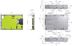
- Standard 3.5″ x 1″ form factor: Width: 101mm, Length: 150mm, Height: 25mm.
- M3 Mounting holes at standard hard disk positions, sides and base. Maximum screw length: 6mm.
Typically, configuration is done once (at the factory) by loading specific microcode into the 1Mbit EEProm. Secondary configuration is done by the customer in the form of SCSI ID and termination set-up.
The internal PCB has a number of internal I/O connectors: a 3 pin serial port and a 16-pin parallel display and pushbutton port. There are also 3 display LEDs:
D1 A green internal surface mount heartbeat LED, that flashes to show that the internal processor is alive. D2 a red LED that shows the presence of termination power on the SCSI bus.
D4 A red 5mm external LED that shows SCSI activity.
D3 A green 5mm external LED that shows ready status for the controller.
When power is first applied to the controller, it performs its own internal self checks, and if these are passed, it flashes the 5mm front panel green LED at a 0.5 second rate. This will continue until a CF card is inserted. The controller senses the card, initialises it and attempts communication with it. If the SCSICFDISK controller can successfully read its CIS area and the Identify data then the controller stops flashing the green 5mm LED.
The card will accept SCSI commands at any time beyond 250 mSec after power-up. The card will remain in a not-ready state until a suitable CF card has been inserted, it has been powered up and its Identify data has been successfully read. The controller will then go ready via the unit attention state.
Configuration & Installation
- Set Termination Disable/Enable at LK2 — If jumpered termination is ENABLED
- Exporting termination power. – This is generally not necessary, but If so jumper LK1. Note that the internal terminators always have power.
- Connect the SCSI cable, noting that pin 1 of the cable is at the edge of the PCB.
- Connect the 5V power. Note that a standard 5V/12V disk power lead can be used here as the 12V pin is a no-connect on the board.
- Note the green heartbeat LED will flash. Also note that the 5mm front panel green LED will briefly flash while the CF card is being initialised.
- Teac SCSI Floppy replacement
- OI Servo panel disk replacements
- HP1000 and 9000 storage solutions
- RZ23 flashdisk for the DEC VAX & UVAX
- SCSI Tape & Disk solutions for Rosemount RS3 systems
- SCSI tape & Disk solutions for Honeywell MXopen
- Garson Industries Flash disk and tape products in NEC Neax Telco Switching applications
- Garson Industries Flash disk and tape products in Siemens EWSD Telephone Exchange Switching applications
- Garson Industries Flash disk and tape products in Telco Switching applications
- SCSICFISKs for IBM AS400 and RS6000 systems
- Garson Industries SCSCFDisk to replace the Sony SMO-F551 and other MO Drives
- Flash Storage Solutions for the ABB Advant Operator Stations,-HP B132L+ and HP B180L computers