Solid State replacements for legacy SCSI Tape drives
- A SCSI tape drive with no moving parts.
- The FlashTape is a Printed Circuit Board (PCB) that emulates a standard SCSI Tape drive. It uses a Compact Flash (CF) Card as its storage. The CF card is plugged into the 3M CF socket at the end of the PCB and this is presented as a regular SCSI Tape to a Host via the SCSI interface at the other end of the board. The CF cards can be removed and used in the same way as the original Tapes.
- The PCB mounts in a standard 3.5″ form factor tray and has a standard SCSI1/SCSI2 interface which can be configured to emulate & replace those hard-to-find SCSI tape drives- DAT/DLT/QIC/9-track/8mm/3490/3590 etc. It requires 5V only which is supplied via a standard power connector.
- Data is stored on an industry standard Compact Flash (CF card), which can be easily removed. The CF card can then be plugged into a PC and the data archived.
When connected to a SCSI Host, the Host sees the FlashTape PCB as a SCSI Tape drive.
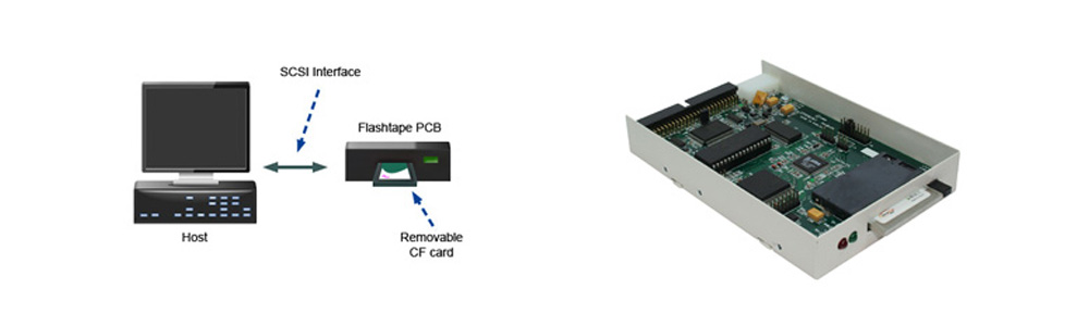
The SCSI bridge PCB carries its microcode in Flash, that can be simply updated via the SCSI or Serial ports. It has an optional standard display module interface to drive a 2 line by 16 character backlit, LCD display.
SCSI 2 transfer rates of (up to) 10 Mbytes/sec, and disk capacities only limited by current CF cards (up to 128GB as of 2012)
As tape drive manufacturers continue to improve the transfer rate performance of their products by increasing the tape-to head speed within the drive. This is often a disadvantage for Hosts with very slow data transfers to tape. It often leads to continual tape repositioning within the drive (shoe-shining). This shortens the life of the mechanics of the drive, and also leads to constant clogging of the tape head gaps from tape debris. The Flash-tape overcomes this issue as it has no moving parts.
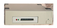
Available in various form factors, with CF eject header, and several subsystem styles.
Tape Emulations exist for most common tape drives…
Archive, Cipher, Colorado Data, Conner, DEC, Exabyte Fujitsu, HP, Sony, Pertec, Qualstar Quantum, SONY, Tandberg, TEAC, Tecmar, Storage Tek, Wangdat, Wangtek, QIC, DLT,8mm 3480, 3490E
Python, Viper, 2105S, 2525S, VP150, 2150S, 2060
VP60S, QIC-150,QIC-120, QIC-525 QIC-24
Anaconda 2750
Python DAT 4320,4322, 4324, 4326, 4520, 4540
Cipher
M990, M995, F420 F-880, F-890, F880, ST350F
Colorado Data
PT-10, PT-25, PT-50, T20i, T4000s, C5645A
Conner
CS250QE, CS525QE, CS2000, CS4000, CTD2004, CTD4004 CTD8000E, CTT8000R, CTM3200, Travan
DEC
TLZ06, TLZ09, TLZ07, TLZ10, TZ86, TZ86, TK70,TK50, TZ89, TZK9, TZK10, TZK11, TLZ88
DDS DAT drives
Exabyte
EXB8200, EXB8205, EXB8500, EXB8505, EXB8705
Fujitsu
M1016B 2483B, 2485 M2513A6U, 3480, 3490, 3490e, M2488
HP
C1533A, C1553A, C1554A, C1503, C1504, C1526 C1537A
C1555, C1556, C1539, C1536A C5583A, C5685A, C5683A
88780, 88781, HP 7980S
Pertec
DDF Pertec
Qualstar
3410
Quantum
DLT2000, DLT4000, DLT7000, DLT8000, SDLT
SONY
SDT-2000, SDT- 2601, SDT-4000, SDT-5000, SDT-7000, SDT-5010, SDX-300, SDX-400, SDX-500, SDT-9000
SDT-5200, AIT1, AIT2
9 track
Tandberg
SLR2.5, SLR2, SLR3, SLR4, SLR5, SLR6, SLR7, SLR24 TDC6287, MLR TDC3820, TDC4120, TDC4220, TDC4222
TDC3660, TDC 3540, TDC4100, TDC4200, TDC6100
DLT4000, DLT7000, DLT8000
TEAC
MT-2ST-45S, MT-2ST-50, MT-2ST-55, MT-2ST-70
MT-2ST-F50B
Tecmar
Storage Tek
STK, STK KS23909L10, 4781
Wangdat
1300, 2000, 3100, 3200, 3400
Wangtek
5125, 5150, 51000, 52000, 5360, 5525, 6130, 6200, 9500
Tape emulations exist for the following systems:
AS/400, DEC VAX, UVax and PDP-11, Encore, Evans & Sutherland, HP 9000 series 800, HP 9000 series 500, HP 9000 series 300, HP 1000 A Series, I/O systems Honeywell Measurex, MX-OPEN, Rosemount RS3, Sercel, Sun Spark ABB Advant Operator Stations, HP B132L+ HP B180L, and several Telco host applications including Ericsson, Siemens EWSD, Fujitsu Fetex 150, NEC NEAX 61E, NORTEL DMS10, and TELEBRAS TROPICO.
 Garson Industries aim the product as a low-cost way to give extra life for Legacy Hosts which would otherwise need to use unreliable second-hand Tape drives.
Overview
- Form Factor: 3.5″ x 1″ hard disk form factor, industry standard hole mount positions M3 threaded.
- Interface: Compliant with SCSI2 standards – ANSI X3. 131-1994.
- Mounting: Any orientation.
- Connector: Standard SCSI 50-pin, Single-Ended (SE). HVD adapter daughter card available.
- CF Card compatibility: Type 1 CF cards via a CFA approved 3M CF socket.
- Ejector: Ejector Option for easy removal of CF card.
- Retainer: Retainer clip option permits stability for mobile and in high vibration applications.
- Reliability (MTBF): in excess of 1,000,000 hours (and counting) (empirical data).
- Parts that wear: CF card eventually wears-out, but this low-cost part can simply be replaced by the end-user.
- Moving parts: None
- Write Protect: Several CF cards with Write protect switch are supported.
- Diagnostic Port1: A serial port with comprehensive diagnostic printout, microcode upload, and SCSI trace capability.
- Diagnostic Port2: A 16-pin parallel LCD display and pushbutton port, that facilitates a menu driven product configuration system.
Power:
- Input Power: Via standard Molex style disk drive connector 5V & 12 V. 12V not used- no connection. 5V +/- 5% @ 500 Ma (depending upon CF Media)
- CF Power: 3V3 via on board regulator.
Environmental:
- Operating Temperature: Commercial operating temperature range from 0%C to +65%C.
SCSI Interface:
- Single-ended 50 pin bus SCSI 2 or SCSI 1 or SASI with many emulations.
- Synchronous & asynchronous transfer capable at Fast SCSI 2 Burst rates of 10 Mbytes/sec.
- SCSI Termination via on board active terminators selectable via a jumper.
- HVD (High Voltage Differential) SCSI interface is possible by using a plug-in daughter card option. On board HVD terminators are also selectable.
Mechanical:
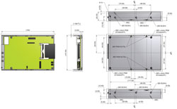
- Standard 3.5″ x 1″ form factor: Width: 101mm, Length: 150mm, Height: 25mm.
- M3 Mounting holes at standard hard disk positions, sides and base. Maximum screw length: 6mm.
Typically, configuration is done once (at the factory) by loading specific microcode into the 1Mbit EEProm. Secondary configuration is done by the customer in the form of SCSI ID and termination set-up.
The internal PCB has a number of internal I/O connectors: a 3 pin serial port and a 16-pin parallel display and pushbutton port. There are also 3 display LEDs:
D1 A green internal surface mount heartbeat LED, that flashes to show that the internal processor is alive. D2 a red LED that shows the presence of termination power on the SCSI bus.
D4 A red 5mm external LED that shows SCSI activity.
D3 A green 5mm external LED that shows ready status for the controller.
When power is first applied to the controller, it performs its own internal self checks, and if these are passed, it flashes the 5mm front panel green LED at a 0.5 second rate. This will continue until a CF card is inserted. The controller senses the card, initialises it and attempts communication with it. If the scsicfdisk controller can successfully read its CIS area and the Identify data then the controller stops flashing the green 5mm LED.
The card will accept SCSI commands at any time beyond 250 mSec after power-up. The card will remain in a not-ready state until a suitable CF card has been inserted, it has been powered up and its Identify data has been successfully read. The controller will then go ready via the unit attention state.
Configuration & Installation
- Set Termination Disable/Enable at LK2 — If jumpered termination is ENABLED
- Exporting termination power. – This is generally not necessary, but If so jumper LK1. Note that the internal terminators always have power.
- Connect the SCSI cable, noting that pin 1 of the cable is at the edge of the PCB.
- Connect the 5V power. Note that a standard 5V/12V disk power lead can be used here as the 12V pin is a no-connect on the board.
- Note the green heartbeat LED will flash. Also note that the 5mm front panel green LED will briefly flash while the CF card is being initialised.
- Using the Garson Industries Flash disk and tape products in Telco Switching applications
- Using the Garson Industries Flash disk and tape products in NEC Neax Telco Switching applications
- Using the Garson Industries Flash disk and tape products in Siemens EWSD Telephone Exchange Switching applications
- Using the Garson Industries FlashTape to replace old tape drives for Vax & uVAx systems
- Using the Garson Industries FlashTape to replace old tape drives for the IBM RS6000 and AS400
- SCSI Tape & Disk solutions for Rosemount RS3 systems
- Tape & Disk replacements for Honeywell Measurex Systems
- Flash Storage Solutions for the ABB Advant Operator Stations,-HP B132L+ and HP B180L computers
- Using the Garson Industries Flash disk and tape products in Nortel DMS10 Telco applications